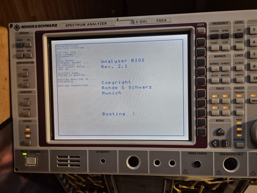
Okay so one of my other related hobbies is repairing older equipment if I see something that looks interesting that would go to e-waste otherwise. I spotted this FSEA 30 on ebay a couple of weeks ago and it piqued my interest:
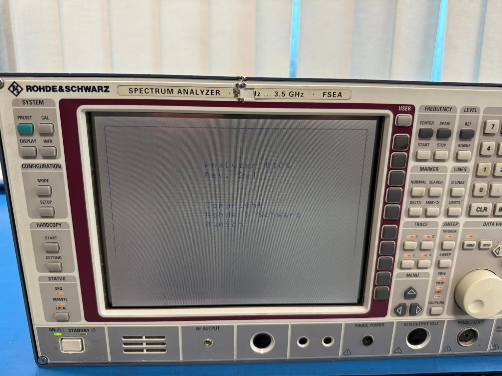
The faults listed were the physical damage to the front panel, fairly minor, failure to boot and a report of a failed hard drive and from the images its clear the display had some serious issues. On powering it up it was even clearer – the display comes on when first powered up then the blue on white text fades away to white within a couple of seconds.
The first task was to address the hard drive issues, so I bought a cheap 2.5 IDE to compact flash adapter and copied an image onto the CF – Inititally this didnt work because some old partitioning was left on the CF but a quick pass with dban cleaned the CF and the image then booted okay.
The oddity with these is that there are 4 parts to the disk, a primary fat 16 partition, an extended partition containing a second fat16 partition and then another primary partiion in Microcode format hosting the iRMX main OS. The image seems to be fairly universal to all these analysers as initially it thought it was an FSIQ as I had one module disconnected as required to get to the pc module. Upon replacing everything picked up fine.
The second issue I noticed once the machine was running again was that date/time was warning and on the main pc board (that hosts a 486 Overdrive and some 30pin simms) there was a 3.6V lithium battery (non rechargeable) which was reading 0v.
I got a replacement (1/2AA 14250 Lithium battery) from amazon but its the regular type whereas this unit has a battery with axial pins that solder direct to raised lugs. I used a battery strip welder to tack on some nickel strips to each and and trimmed to length. soldered in and retained with a cable tie as per the original.
Time was now being set, so the next issue was the screen. The screen is an FRZ12005 which seems to be used in a few R&S devices and some other industrial equipment. These panels are available on some marketplaces but the symptoms led me to believe it might be worth investigating.
The Panel has a control board on the right hand side (when viewed from behind) with two connectors – a 15pin (CN11) and 10pin (CN12) that go to the main board.
There are also three flex cables that go to the panel itself:
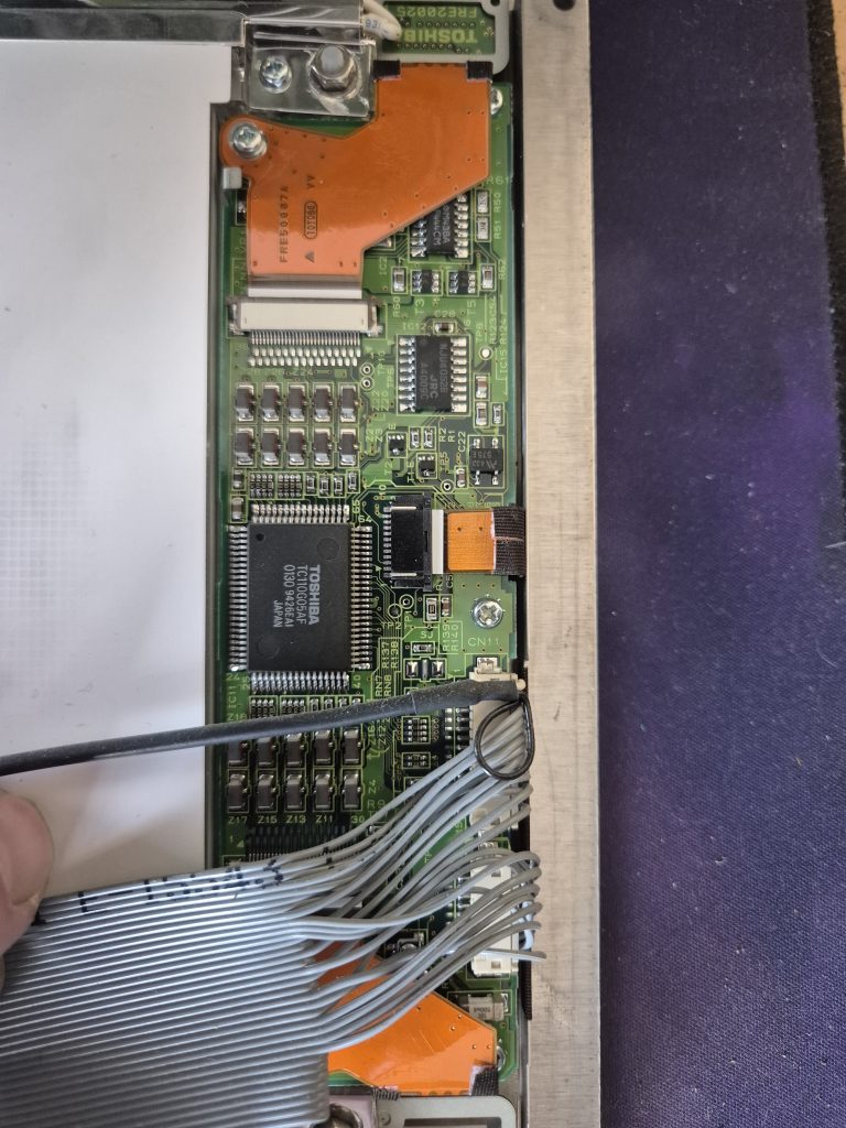
Visual inspection from above showed no signs of any kind of power regulation/generation and these panels need a couple of elevated voltages to drive the lcd itself. Typically these are around 15v and around 24v. So accepting that I could just source another expensive panel if it was beyond repair I thought I’d have a look underneath.
To remove this PCB from the lcd panel you’ll need to remove the two screws that hold down the flex on the top and bottom first. then you’ll need to release these flexes, by pulling the retaining clip back and sliding out the flex. Once that’s done there’s the middle flex to release – again a sliding retention clip. Being that the flex seemed to tight radius wise and this is a 30 year old flex i opted to remove the board so i didn’t put too much strain on the flex. To do that there are three screws, 2 are under where the two flexes we’ve just disconnected and the other is in the middle. To get the PCB out you’ll need to lift and push slightly to the right to get over the retaining posts on the module.
Once it comes out the remaining flex will easily slide out and the bottom reveals the power supply section:
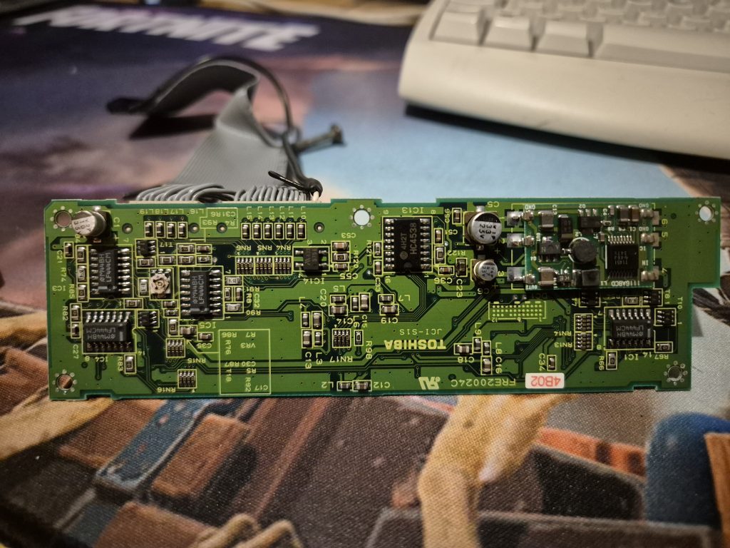
The raised module on the right looks like a standard buck converter module which produces two outputs. The outputs are filtered by a pair of electrolytic caps – OUT1 has a 33uF 25V electrolytic and an MLCC of unknown value – this will just be high frequency filtering. OUT 2 has a 4.7uF 33V electrolytic and an MLCC of unknown value.
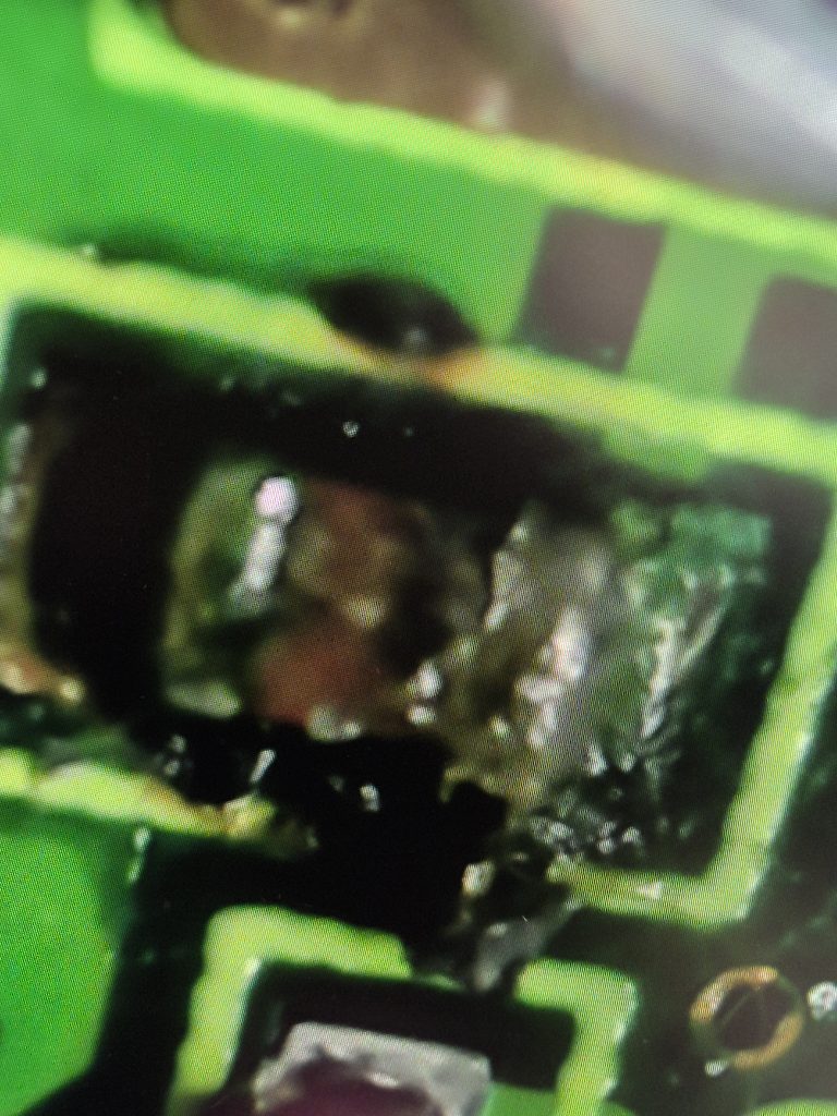
The eagle eyed may have spotted something on OUT2 (as did I) and that appears to be the MLCC seems to have failed quite badly – C23 is both discoloured and there is burnt residue (which isn’t that clear on the picture). I assume that what’s happening when this turns on is the electrolytic is struggling to maintain output as the MLCC puts a load on the electrolytic causing the voltage to drop resulting in the text fading on the LCD.
I removed the cap using a pair of SMD soldering tweezers, and used some IPA to clean the residue. I then applied fresh flux and solder and used solder wick to clean the pads up and applied IPA again. I then located an appropriate (to my mind) MLCC – 220nF was the only 50V I had to hand, probably 100nF would have been okay. I went for 50v As I assumed this circuit is probably producing the 24V (or thereabouts) so the designers didn’t opt for a 25V electrolytic as the safety margin would be too low.
I resoldered the MLCC and cleaned up – ideally I would have replaced the electrolytics there as well but I didn’t have any to hand that matched, and couldn’t find any component value issues around that circuit so i thought I’d see what effect this had.
I reassembled the pcb taking care to insert the flex in the middle before fitting but not closing the retention clip. Once in i secured using the three screws (middle and one under each flex.then I closed the retaining clamp, fitted top and bottom flexes, closed clamp and inserted the screws. front panel was re-attached to the analyser and the result?
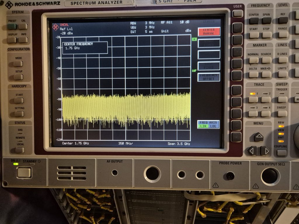
I nopw just have a single voltage issue thats being picked up by self test as being under range:
18/0 MUX 12.0: 0.053V, limits 0.10..6.00V
Calibration fails on ‘RFModul – RF-Converter’, but that voltages appears to be a 2nd IF voltage.
Unfortunately R&S dont supply any real schematics so I’ll be engaging in a bit of a wild goosehunt soon, the analyser works but I think signal attenuation is off but I need to find and fix this fault before I can check for sure.
Anyway I hope this is useful for someone else in the future – its an FRZ12005 display which is common on I think all FSE A/B/K/M etc and the FSIQ analysers.
Leave a Reply